Table of Contents
Mega Drive Single-Switch Region Mod
There are many excellent guides on the internet about region modding the Sega Mega Drive. However, these guides all have one thing in common: they describe the installation of two switches on the Mega Drive to control the console's language and TV settings separately. Whilst experimenting with the knowledge gained from these guides, I discovered that you can actually control both settings with a single three-state switch. This makes the assembly much cleaner and simpler, requiring you to solder only three wires, and you end up with one easy-to-use switch that does exactly what you want: switch between American, European and Japanese.
Before we start, I want to emphasize that I'm in no way an experienced electrical engineer. In fact, I barely know how to hold a soldering iron. All it takes to pull this mod off is a clear head and a bit of common sense.
The theory
As you may or may not know, the region of a Mega Drive console is determined by two different settings on the console's motherboard: the language (English/Japanese) and the TV system (PAL/NTSC). Each combination of settings spells out a different region type, according to the following rules:
| Language | TV System | Region |
|---|---|---|
| English | NTSC | America |
| Japanese | NTSC | Japan |
| English | PAL | Europe |
The fourth combination (Japanese + PAL) does not exist in practice, so it can be ignored. These settings are used by the console to determine what kind of signal it should send out to the TV and by games to determine what language they should display. However, many newer games (from 1992 and later) also use these settings to prevent themselves from being played on consoles from a different region. For example, try to play an American cartridge of Street Fighter II on a European Mega Drive and you'll get a message saying it was not intended to be played on that console.
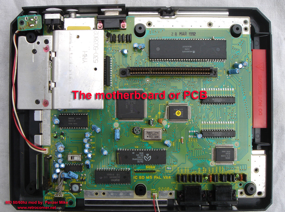
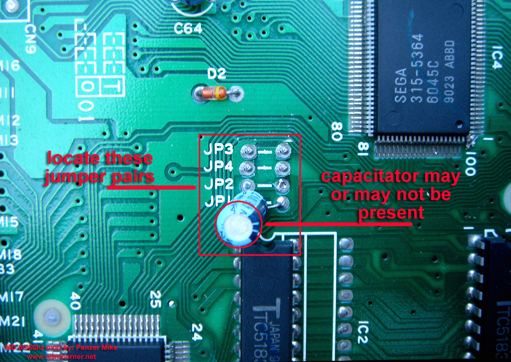
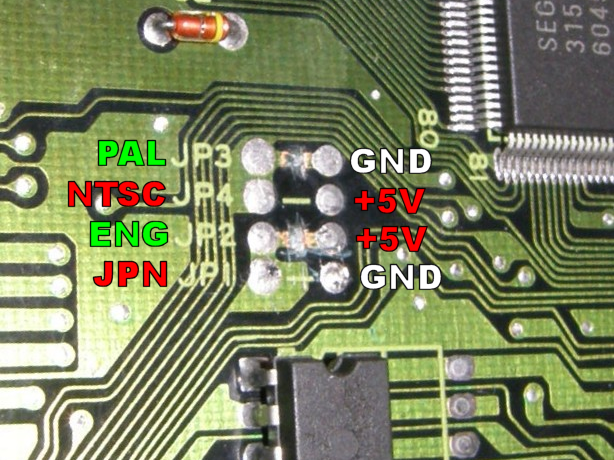
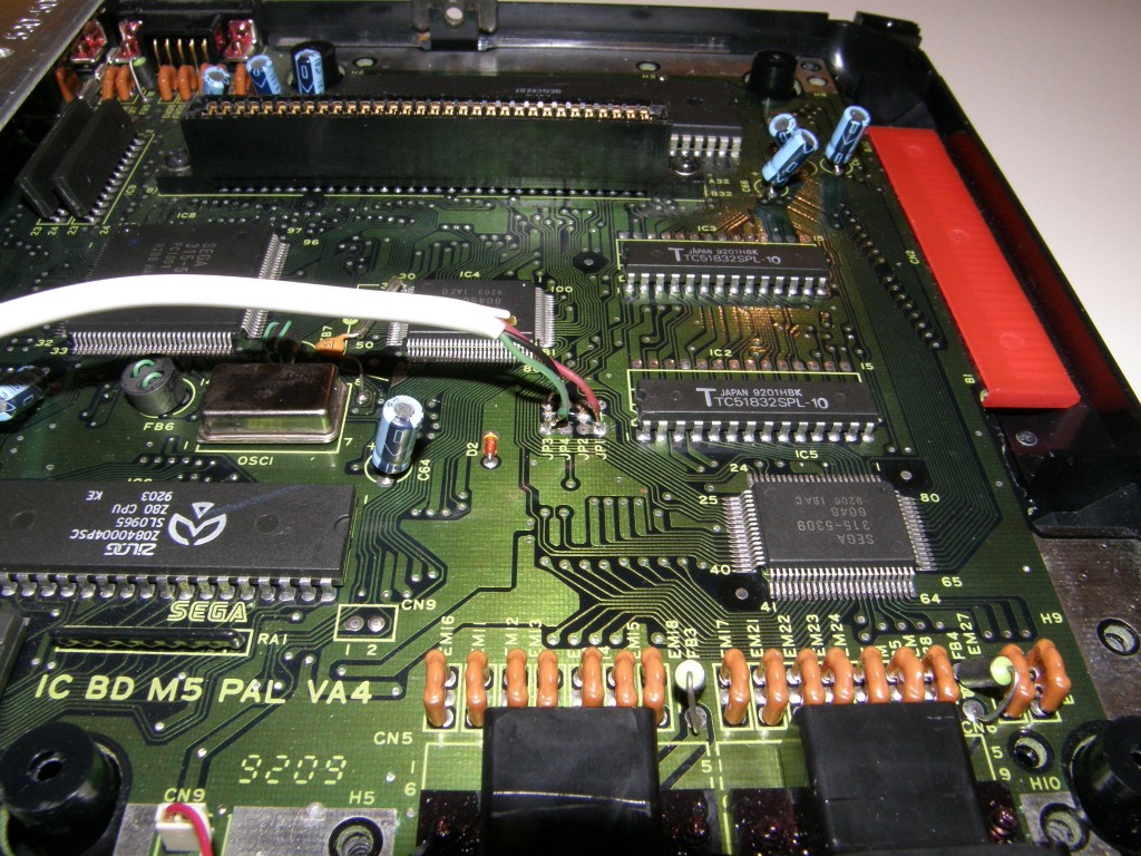
The language and TV system settings are preset in hardware through a series of jumpers. These are visible on the motherboard as four rows of solder pads, some of which are connected by traces etched on the PCB. The pictures below show these jumpers in their original state on a European Mega Drive, as well as their location on the motherboard.
The jumpers may be located in a different place on the motherboard, depending on the exact motherboard revision, and they might be in a different order. Their function remains the same on all model 1 Mega Drives though. As it happens, I have the same Mega Drive revision (VA4) as Mike from The RetroCorner, so you will see the same jumper layout appear throughout this guide.
Although they look like four separate jumpers, in reality the left sides of JP1 and JP2 are connected on the bottom of the motherboard, and the same goes for JP3 and JP4. So they are in fact more like two separate jumper pairs, and connecting either pair to a +5V or ground signal will determine its setting. JP1 and JP2 control the language setting, while JP3 and JP4 control the TV system setting. This leads to the following possible combinations:
| JP1/JP2 (Language) | JP3/JP4 (TV system) | Region |
|---|---|---|
| +5V (English) | +5V (NTSC) | America |
| GND (Japanese) | +5V (NTSC) | Japan |
| +5V (English) | GND (PAL) | Europe |
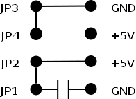
By default, the jumpers on a European Mega Drive are wired as shown in the schematic on the right. What the capacitor on JP1 is for? I haven't got a clue, to be honest. Nobody really knows, as far as I can tell. Newer MD models don't have the capacitor and removing it doesn't do any harm. Leaving the capacitor in place can cause the console to enter a weird English-Japanese-hybrid state at times and has some other odd side-effects, so it is better to just remove it and be done with it.
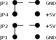
Every Mega Drive region mod starts by cutting the traces on JP2 and JP3. If you do that and remove the capacitor on JP1, you get a 'blank' state where all the jumpers are fully disconnected, as shown below. The jumpers are then free to be rewired as we see fit.
Now most guides will tell you to wire up two separate switches, one for each jumper pair, that switch between a +5V and ground connection. But here's the trick: it turns out that if you leave a jumper pair disconnected, its signal is automatically pulled up to +5V. That means that in this 'blank' state, both jumper pairs act as if they were connected to +5V, so the console will actually default to the American region setting! To switch to either Japanese or European, all you need to do is connect one jumper pair to ground, and just leave the other jumper pair disconnected.
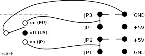
We can easily implement all of this using a simple on/off/on switch. In the central 'off' position, the switch leaves all the jumpers disconnected, making the console default to American. In one 'on' position, JP1/JP2 is connected to ground, making the console Japanese. In the other 'on' position, JP3/JP4 is connected to ground, making the console European.
So the switch we're going to make will look like the schematic shown above. Three wires, one switch. That's all there is to it!
The ingredients
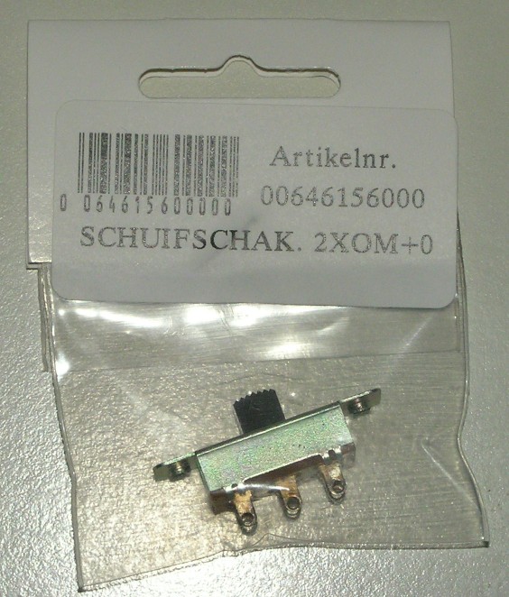
- One on/off/on switch. I used a slide switch, but a toggle switch will work too.
- Three pieces of wire, preferably different colored ones. I used an old telephone cable, which makes for a nicely bundled set of wires.
- A small-ish Phillips screwdriver for opening up the Mega Drive.
- A wire cutter and stripper.
- Soldering equipment and some basic soldering skills.
- One or two files. Having both a coarse and a fine file will make your life much easier.
- (Optional) A sharp knife.
- (Optional) A small drill.
- (Optional) Glue. I used polyurethane (PUR) glue for my mod, also known as Gorilla Glue in the US.
The construction
First, open up your Mega Drive and cut the traces on JP2 and JP3. The guide on The RetroCorner already explains well how to do all this, so I don't need to repeat it here.
Remove the capacitor on JP1. Just heat up the solder pads around its legs and you can pull it out. Alternatively, you could cut the legs with a wire cutter, but personally I don't like such destructive methods. This should leave you with the jumpers in the 'blank' state I showed earlier.
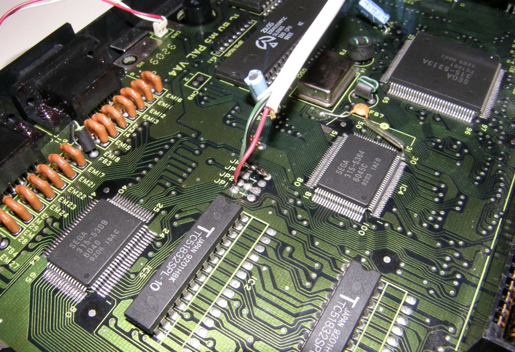
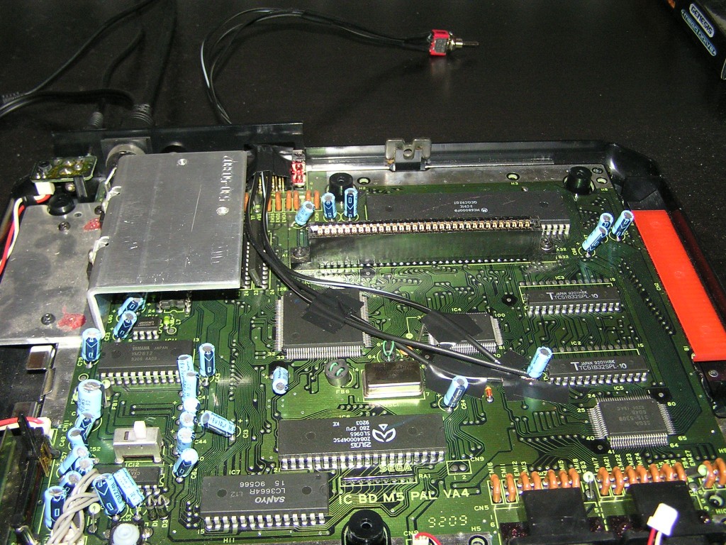
Next, you will have to solder the three wires to the motherboard. I used the following color coding for my wires: black for ground, green for Europe, red for Japan. Solder the ground (black) wire to either one of the ground contacts; I used JP3's ground contact, but JP1 will work too. Solder the Europe (green) wire to the left-hand contact point of either JP3 or JP4. Since those contact points are connected with each other, it doesn't really matter which one you choose. Finally, solder the Japan (red) wire to the left-hand contact point of either JP1 or JP2.
Note: the contact points are actually holes in the motherboard, so instead of soldering the wires on top of them, you can just push the wires through them. Also, don't forget to put some flux and tin on the wires before soldering!
At this point you have to make the final decision where you want to place the switch and how it should be oriented. Initially I wanted to place the switch in the back of the case, but there wasn't a lot of room there and the wire would've clashed with the metal shield. After some deliberation, I decided to place the switch on the left side of the console, where there's a lot of empty space and the metal shield does not interfere.
Now that you know where to place the switch, cut the wires to the appropriate length. Try to leave a bit of margin on the length, so you can play with the routing of the wires. You can always add a few extra bends later to get rid of any excess wire.
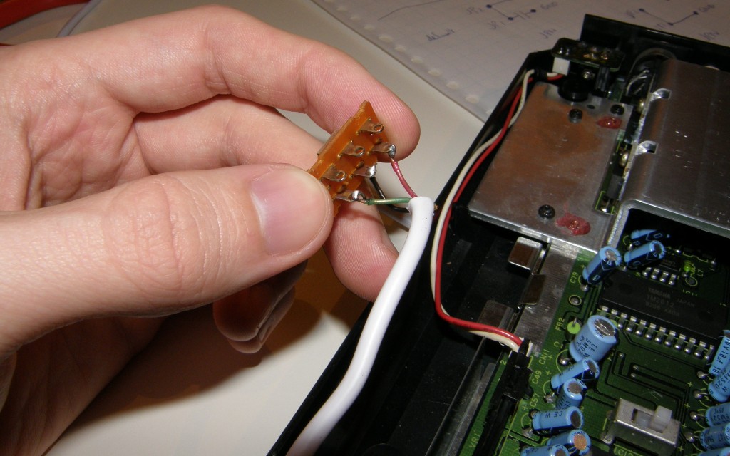
Next, you must solder the wires to the switch. The ground (black) wire should connect to the common pin in the middle, while the Europe (green) and Japan (red) wires connect to the outside pins. I oriented the wires so that the European setting has the switch set to the front position, while the Japanese setting has the switch to the back. Again, don't forget to add some flux and tin before soldering.
At this point it would be a good idea to hook up the Mega Drive and test if your switch works as expected.
As you can see, my switch is a double pole switch, so it has an extra separate row of contacts that isn't used for this mod. I might use it later to wire up a multi-colored LED that shows a different color for each region, or to switch the on-board oscillator to the correct frequency. But that's another story for another time.
Next, you will have to make a hole in the outer casing for the switch to pop through. If you can take apart the switch, you can use the metallic front piece as a template to mark where the hole should go. Use a sharp knife to carve the outline of the hole on the inside of the case. Now make an initial hole that is big enough to get your file through. Ideally you should use a drill for that, but I went the quick and dirty route and melted through the plastic case using a hot soldering iron. Then, start filing away until the hole is big enough so that the switch can fit through and move to all its positions.
I forgot to take a picture of the finished hole, but you get the point. You will see the hole I made appear in the next couple of pictures.
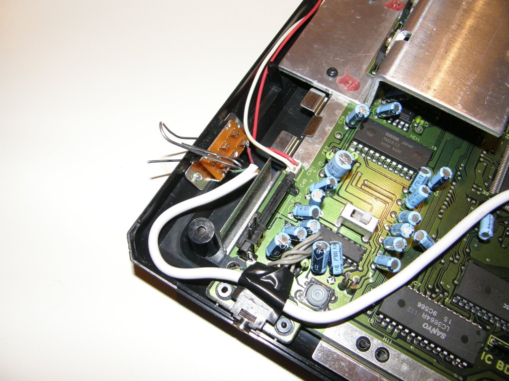
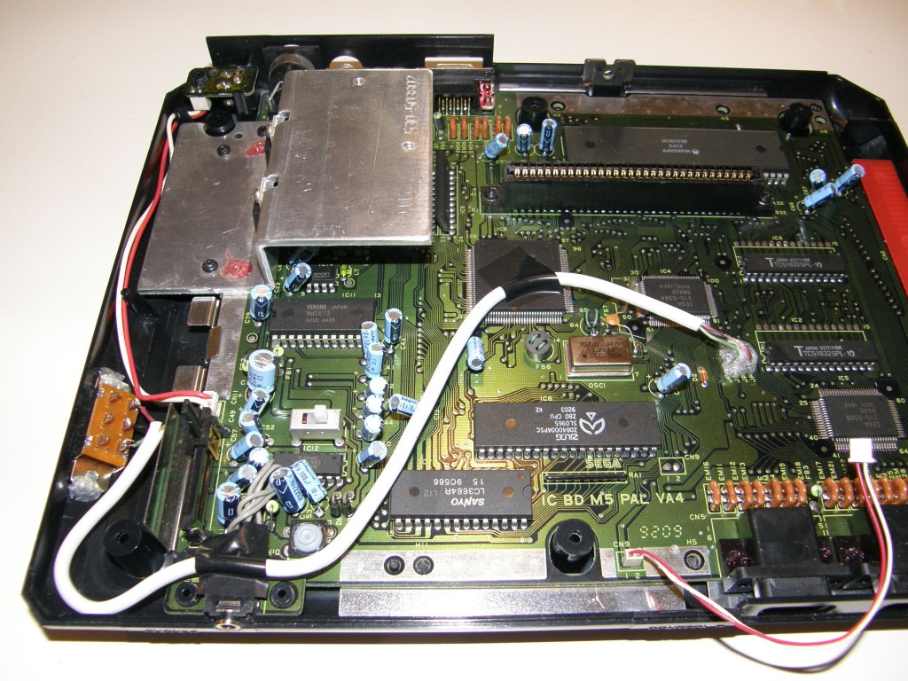
Here I glued the switch to the inside of the case. The PUR glue that I used expands as it dries, so it fills up all the gaps nicely, and it creates a pretty strong bond too. If you don't like the permanency of glue, you can of course use some screws instead. The advantage of glue is that you don't see anything of it from the outside. (Note, the bent paper clip you see in the photo was only there to hold the switch in place while the glue dried.)
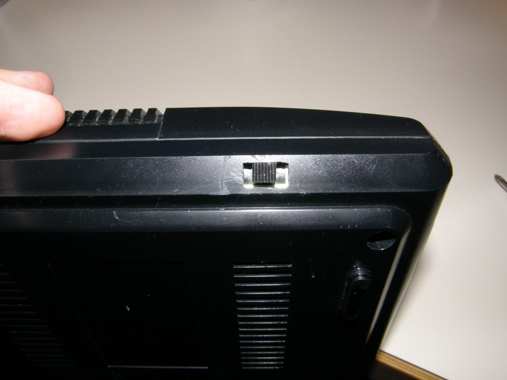
This is the switch poking through the hole after the glue dried. It's not quite perfectly centered, but you usually won't see the switch so that's okay.
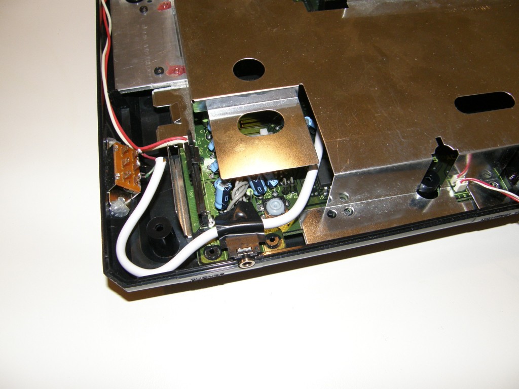
As you can see, the wire snakes around several screw holes, over the headphone plug and alongside the reset button. I took care not to let the wire interfere with either the metal shield or the top of the case when closing the console. After I made sure the wire fit perfectly, I taped it down using a bit of insulation tape to hold it in place.
I also put some PUR glue on the wires soldered to the motherboard, to keep them properly insulated and for some extra solidity.
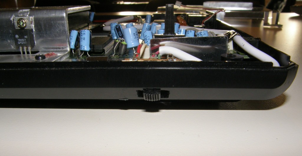
Here you see the metal shield when it's placed back. With the switch and the wire in this position, the shield slides neatly around the whole construction. This way the console remains easy to open up, in case I ever want to modify something else in the future.
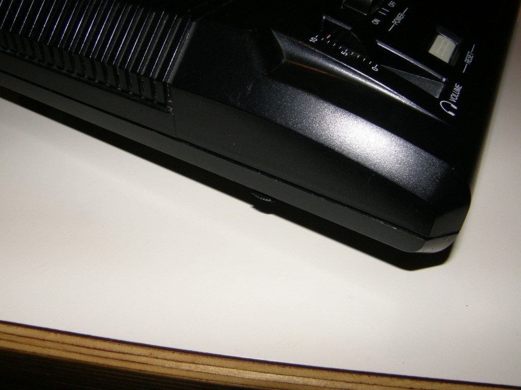
And this is the finished switch. While I would have preferred the switch to be on the back of the case, I have to say it its presence on the side is very subtle. When you look at the Mega Drive from the front, you hardly notice the switch is there.
Bonus
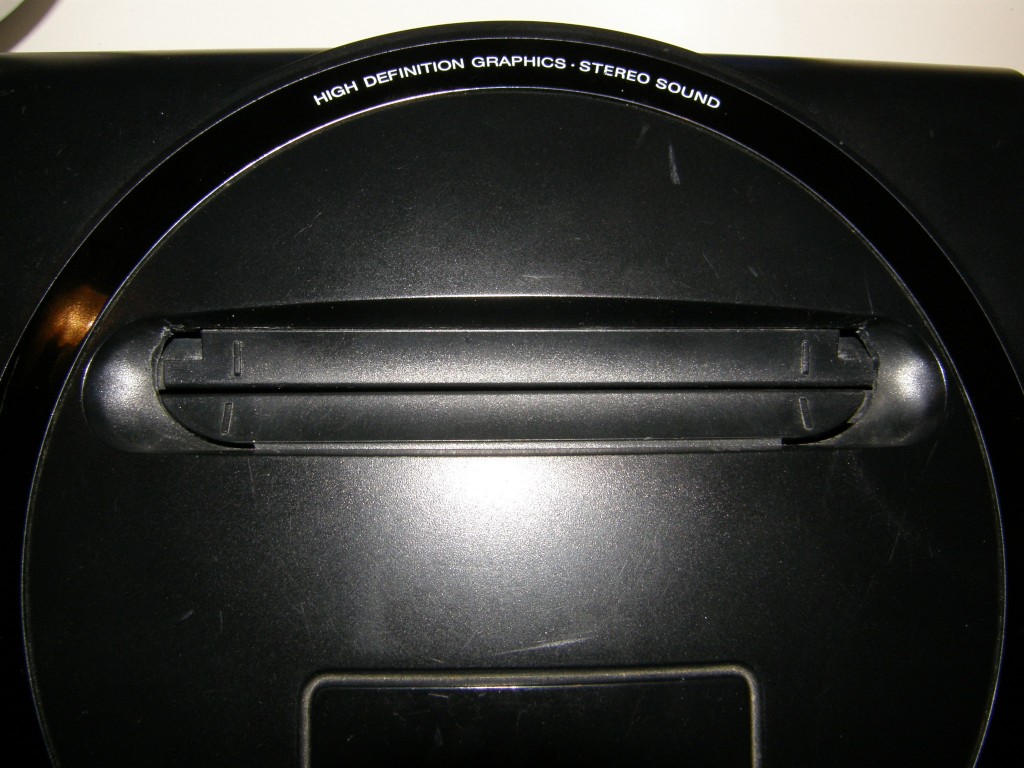
While I was at it, I also filed off the small corner tabs on the cartridge slot and widened the curves at the bottom a bit. This way, Japanese import cartridges fit without the need for a converter.
The following YouTube video shows the single-switch region mod in action. Note that this recording was made using an early prototype implementation that involved a toggle switch, some speaker wire and lots of insulation tape.
Properly soldering down the wires solved the instability of the Japanese mode when starting up Streets of Rage 2. Also, the delay you see in Sammy/Skate's name change when switching from Japanese to American, was caused by the capacitor on JP1. Now that the capacitor is removed, the change is instantaneous. Overall, the finished mod is a lot more stable and consistent than this early prototype mod.
Thanks
- Ace from Sega-16 for writing an excellent guide on the different Mega Drive/Genesis models out there.
- Mike from The RetroCorner, mmmonkey, and DjoeN for their outstanding guides on Mega Drive modding. These guides were the basis of my work here, and I couldn't have done it without them.
- My father for providing me with soldering tools and some helpful assistance.
© Copyright 2009-2010, 2015 by Nico de Poel aka Devil N
